Non-Destructive Testing
Vector Corrosion provides non-destructive testing services to help owners and project teams better understand the condition of their structures, identify active deterioration, and reduce uncertainty when planning repairs or maintenance.
In environments like the UAE, where heat, humidity, and chloride exposure can accelerate corrosion, these methods are critical for identifying issues before they become visible. Traditional inspection methods such as visual assessments and hammer sounding mainly identify surface damage, while deeper or early-stage issues may not be visible.
Non-destructive testing allows for a more comprehensive evaluation of both surface and subsurface conditions, helping uncover early-stage corrosion, internal defects, and unknown as-built details.
Methods
Visual Condition Assessment / Defect Mapping
Visual inspection, including defect classification and mapping, is an initial stage of most condition assessments. Our team uses Plan Radar© for digital capture and quantification of defects.
Acoustic Tomography
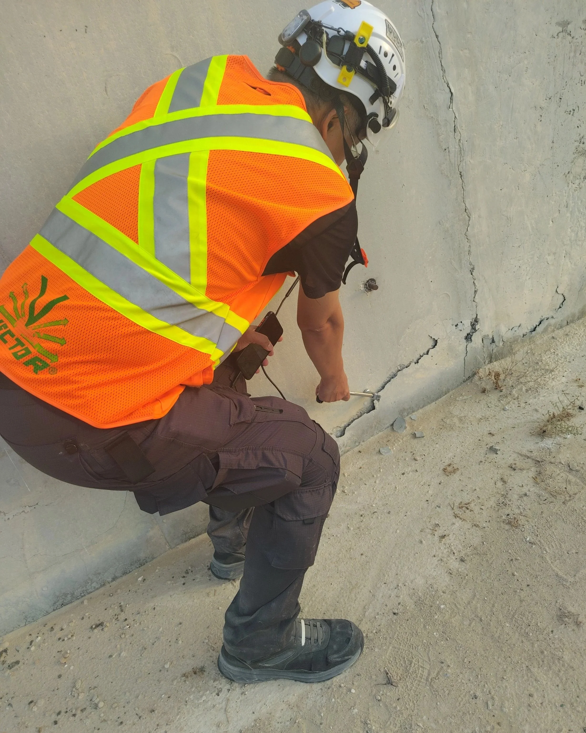
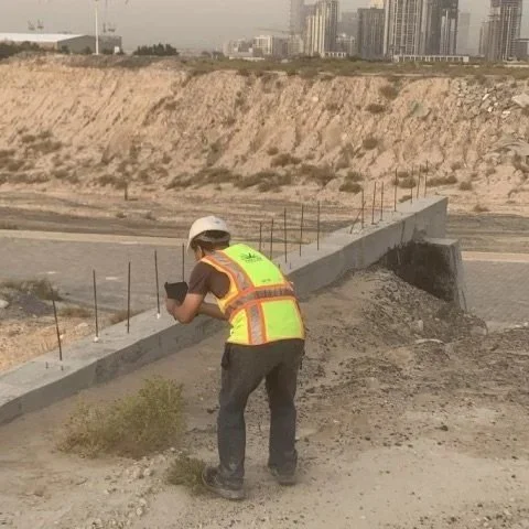
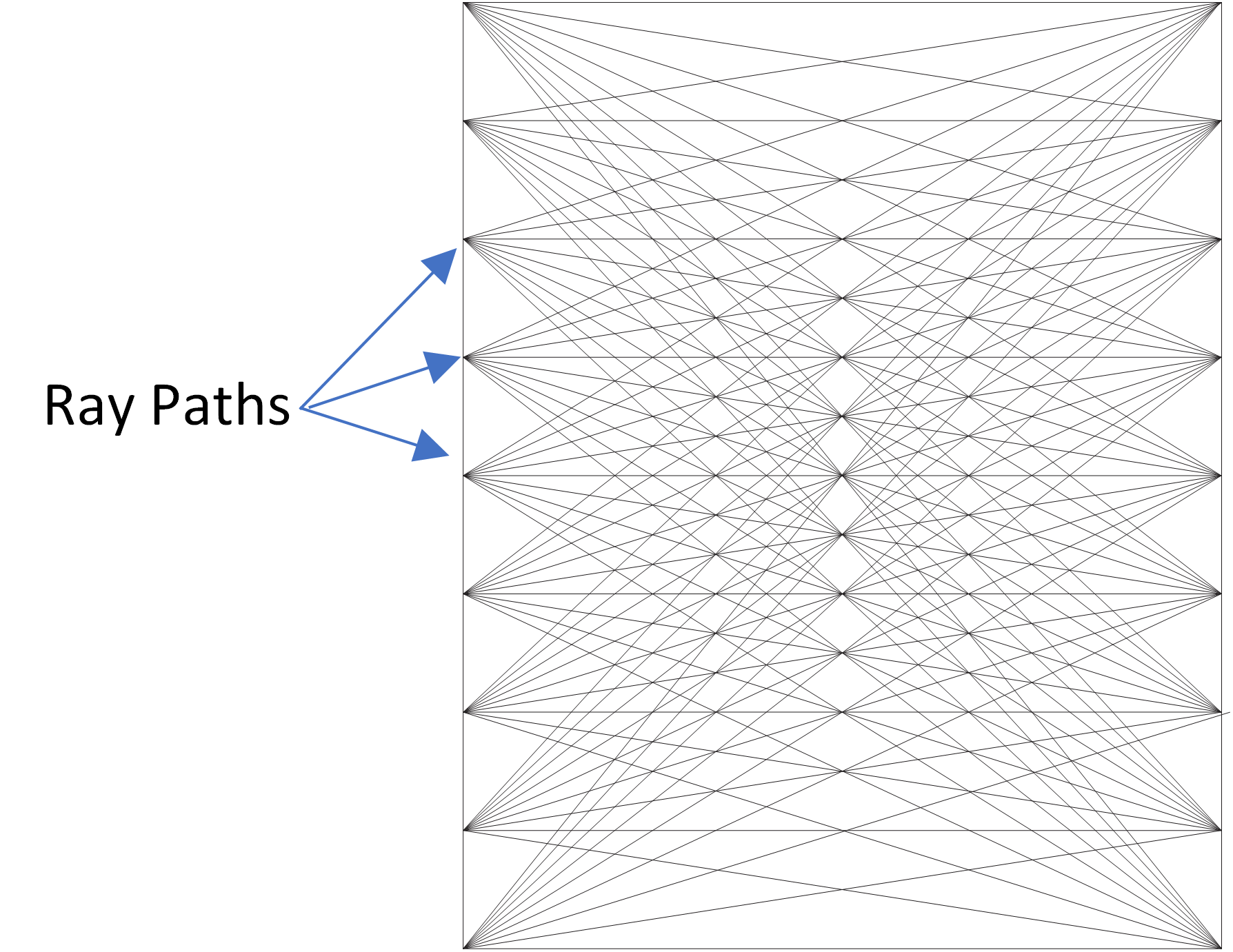
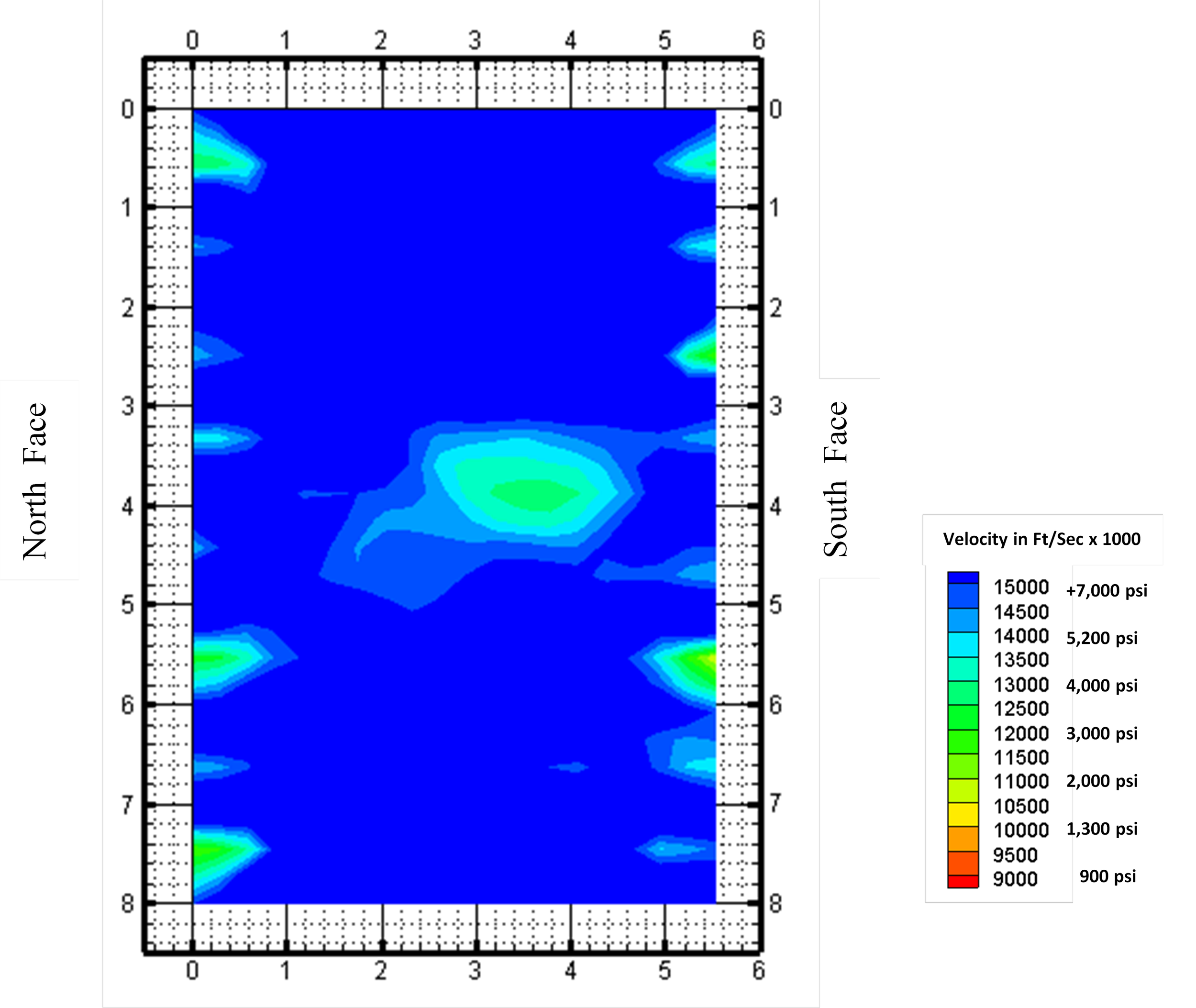
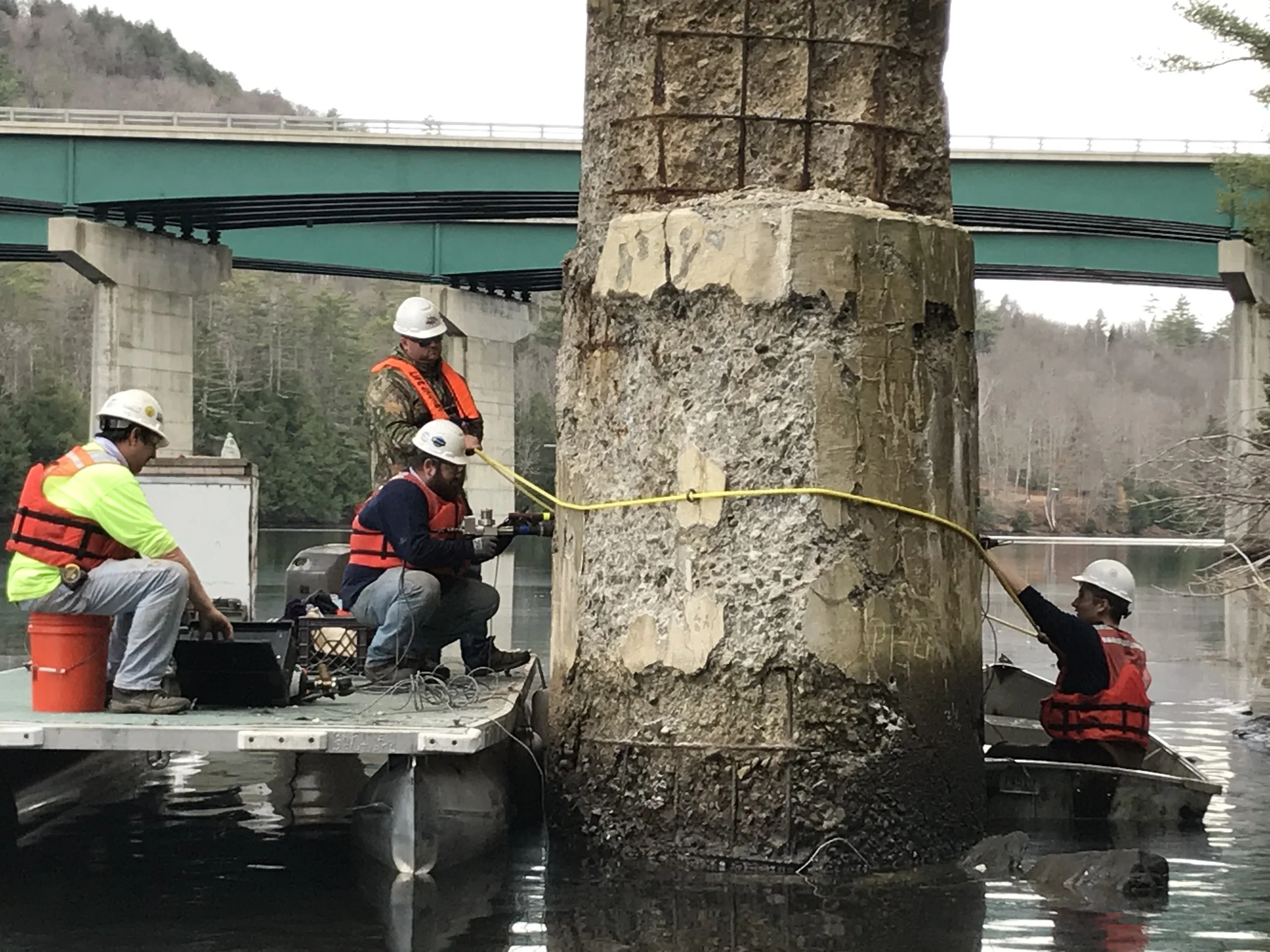
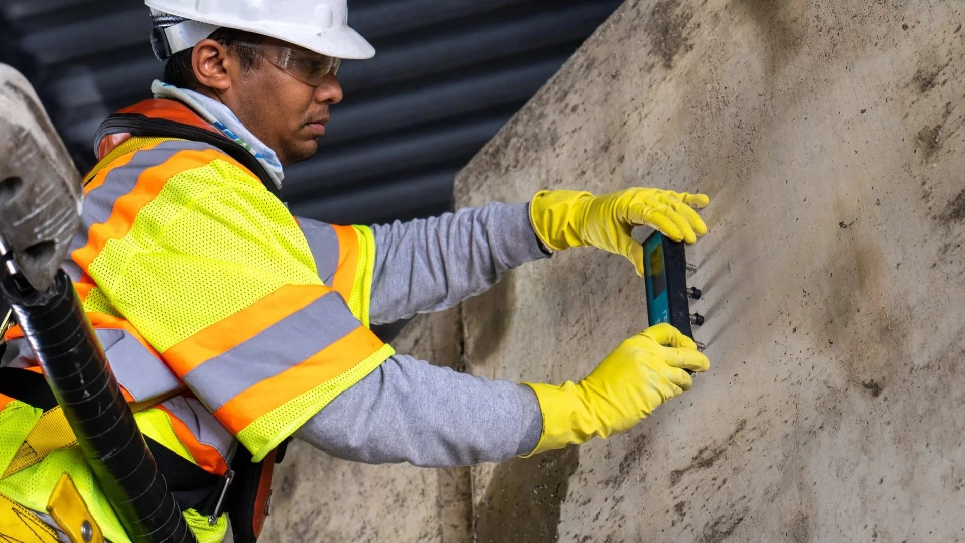
Generates 3D imaging of concrete elements to locate internal defects such as voids, cracking, and honeycombing. This method uses specialised acoustic transmitters and receivers to measure how stress waves travel through the concrete, with slower velocities indicating potential damage.
Concrete Resistivity
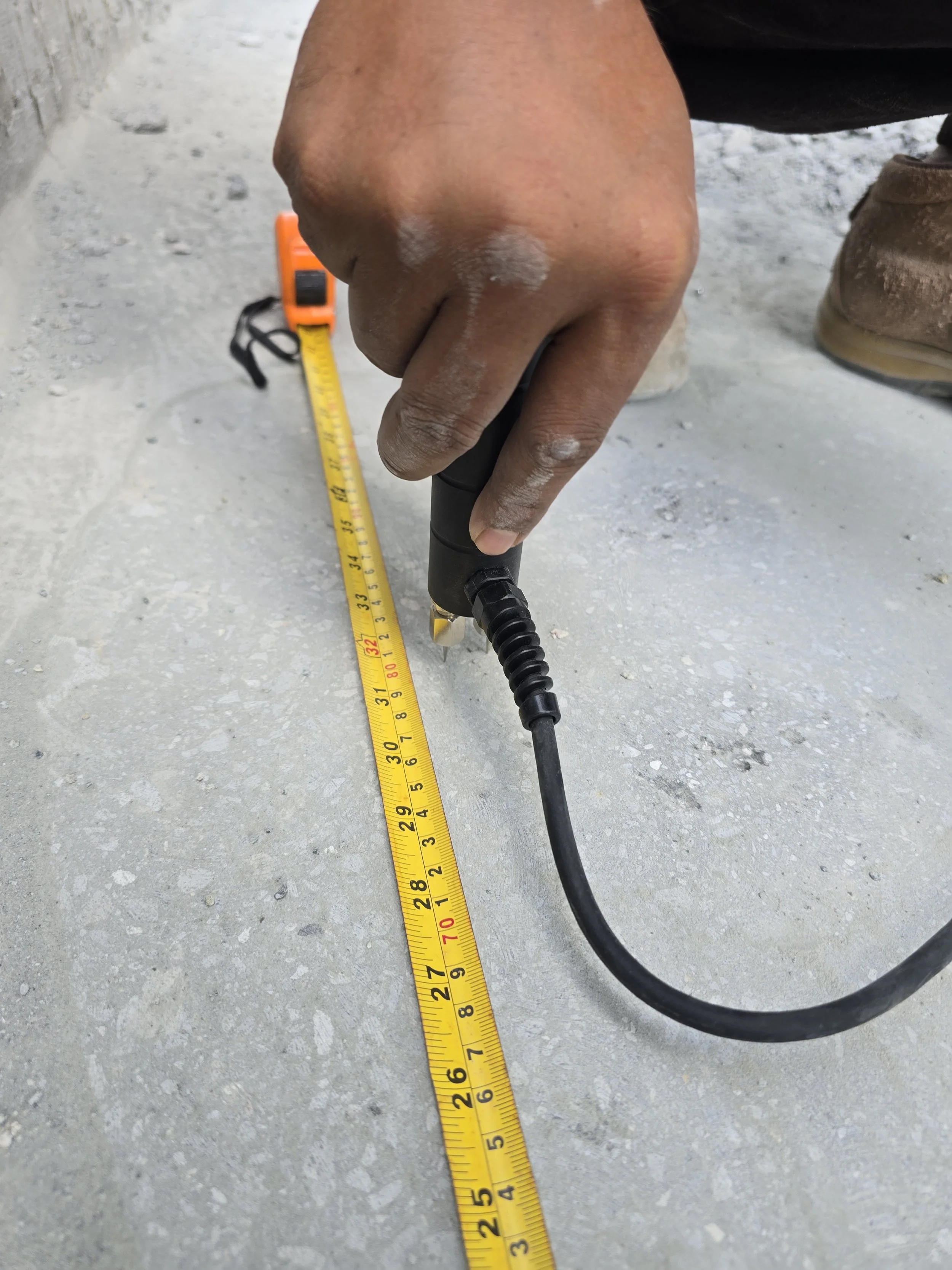
Identifies areas more susceptible to corrosion by evaluating how easily electrical current flows through the concrete using a surface resistivity meter (Wenner probe). This information helps determine how current will be distributed through the structure, allowing for more effective cathodic protection system design.
Corrosion Potential Mapping
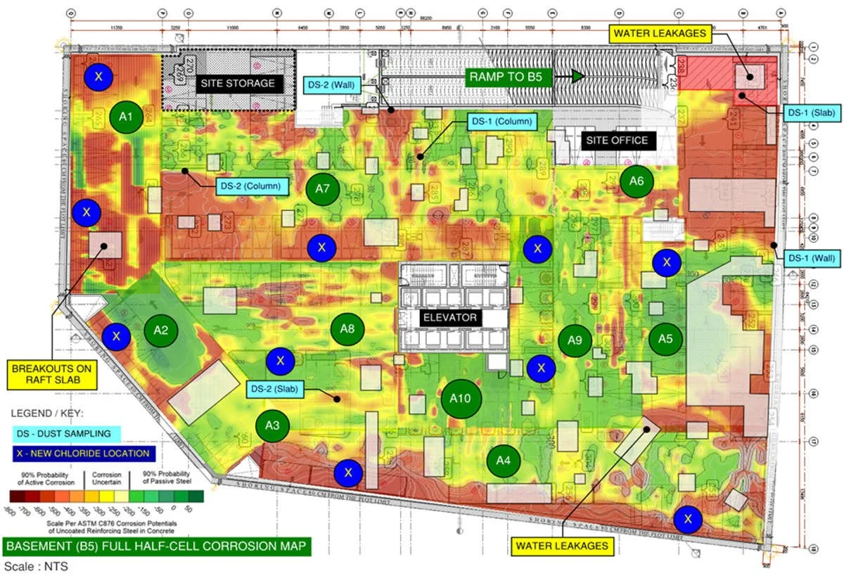
Creates a visual map of corrosion activity across reinforced concrete structures, helping prioritise repairs and understand the extent of deterioration. Measurements are collected across the surface using a reference electrode to identify differences in electrical potential, which indicate where corrosion is more likely to be occurring. This allows owners and engineers to clearly see how corrosion varies across each structural element, supporting targeted repair strategies and cathodic protection design.
Corrosion Rate Testing
Measures how quickly steel reinforcement is deteriorating. A small electrical signal is applied to the steel, and the change in voltage is measured to determine how active the corrosion is. This helps identify areas where damage is progressing faster and where more immediate repair or protection may be required.
Stray Current Surveys
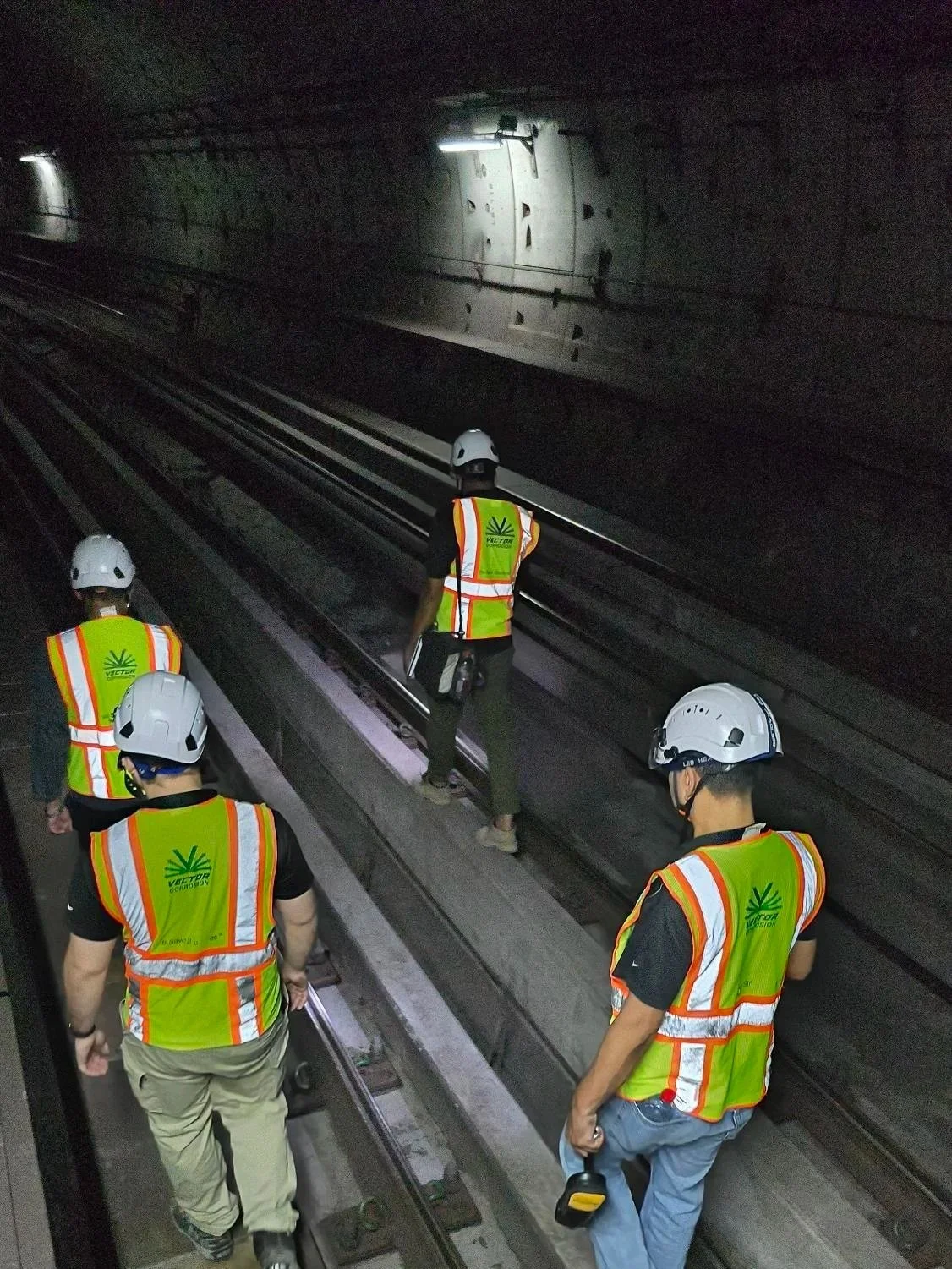
A stray current survey is a systematic field investigation used to detect and characterise unintended DC electrical currents entering, leaving, or flowing through reinforcing steel and other metallic components of a concrete structure. The survey typically includes measurements of structure-to-electrolyte potential, current flow, and electrical continuity to identify the presence, magnitude, direction, and likely source of stray currents and to determine their potential impact on reinforcement corrosion or cathodic protection performance.
Moisture Testing
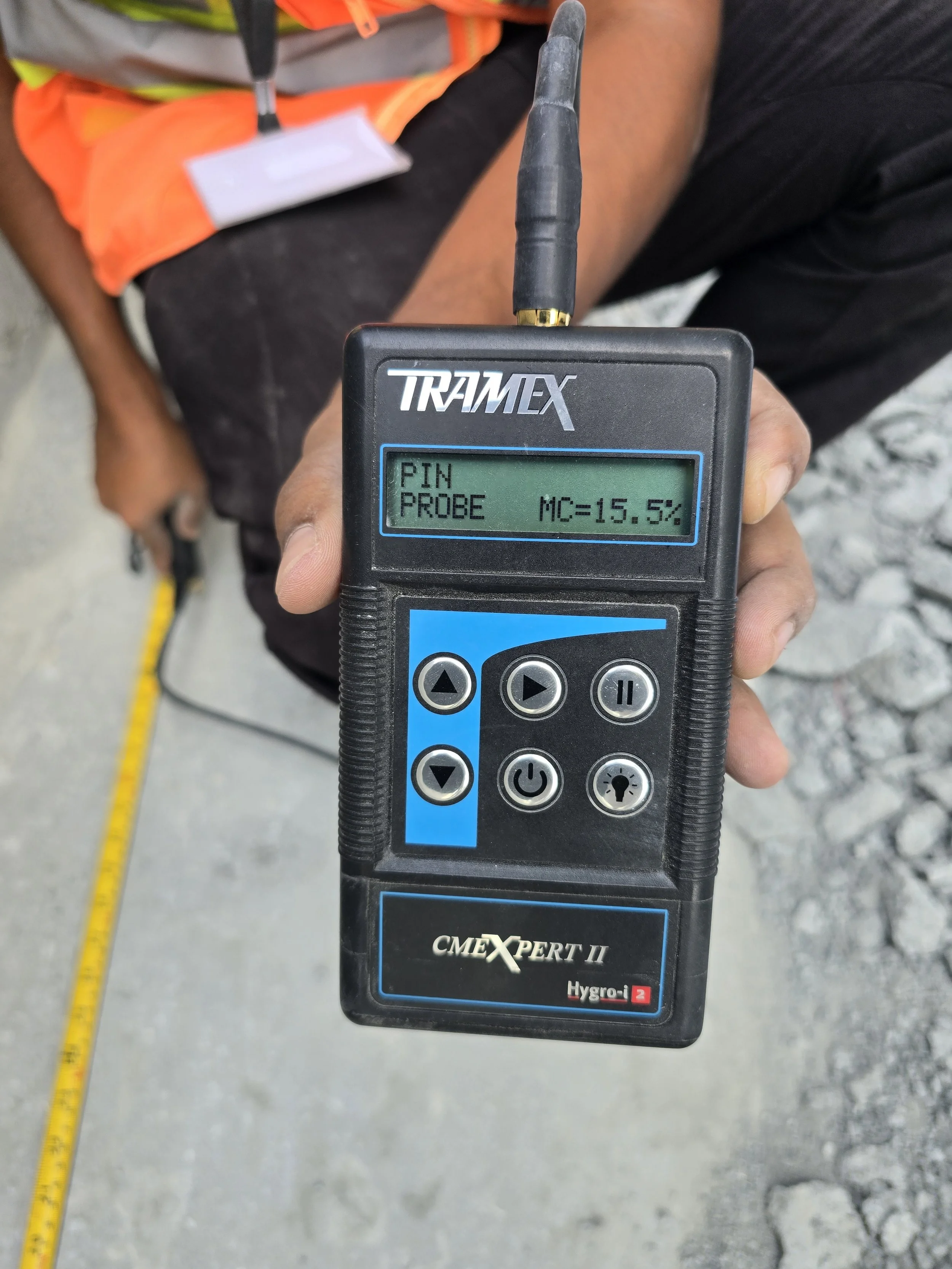
Moisture testing is a field investigation used to characterise the moisture condition of concrete at representative locations, including the presence, distribution, and relative level of moisture within the concrete. The results are used to assess how moisture may influence reinforcement corrosion, electrochemical measurements, concrete resistivity, repair-material performance, and the operation of corrosion mitigation systems.
Ground Penetrating Radar (GPR)
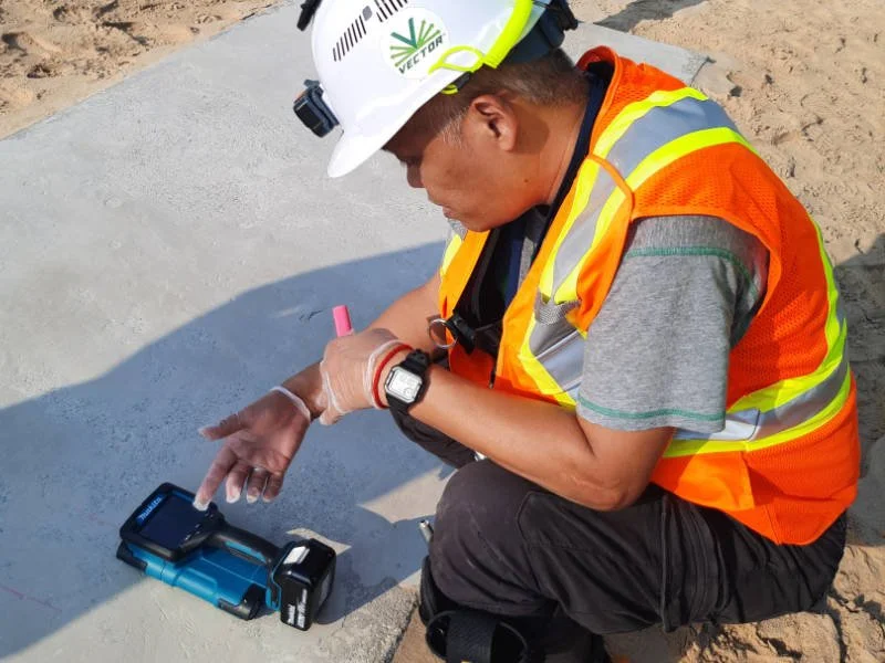
Locates reinforcement, measures cover depth, and identifies as-built conditions within concrete. GPR uses electromagnetic waves to scan below the surface, enabling rapid assessment of large areas and helping project teams understand what is inside the structure. This reduces risk during repairs or modifications by minimising unexpected conditions.
Impact Echo / Pulse Velocity (IE/PV)
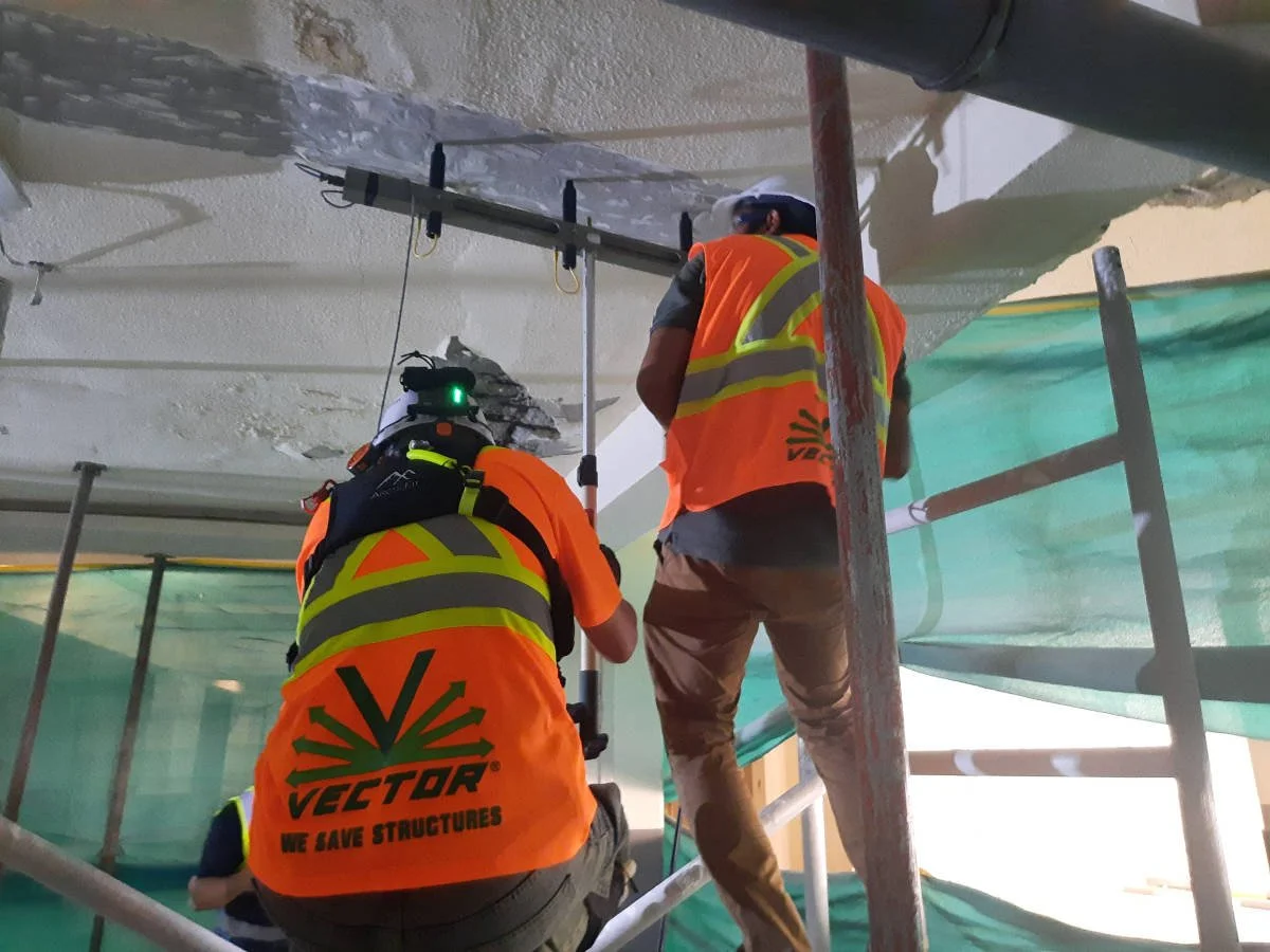
Identifies internal defects such as honeycombing, cracking, and delamination, while also providing insight into in-situ concrete strength. This method uses a small impact and sensors to measure how stress waves travel through the concrete. Vector Corrosion utilizes advanced equipment designed to collect both impact echo and pulse velocity data simultaneously, improving efficiency and providing a more complete assessment of the structure.
Infrared Thermography
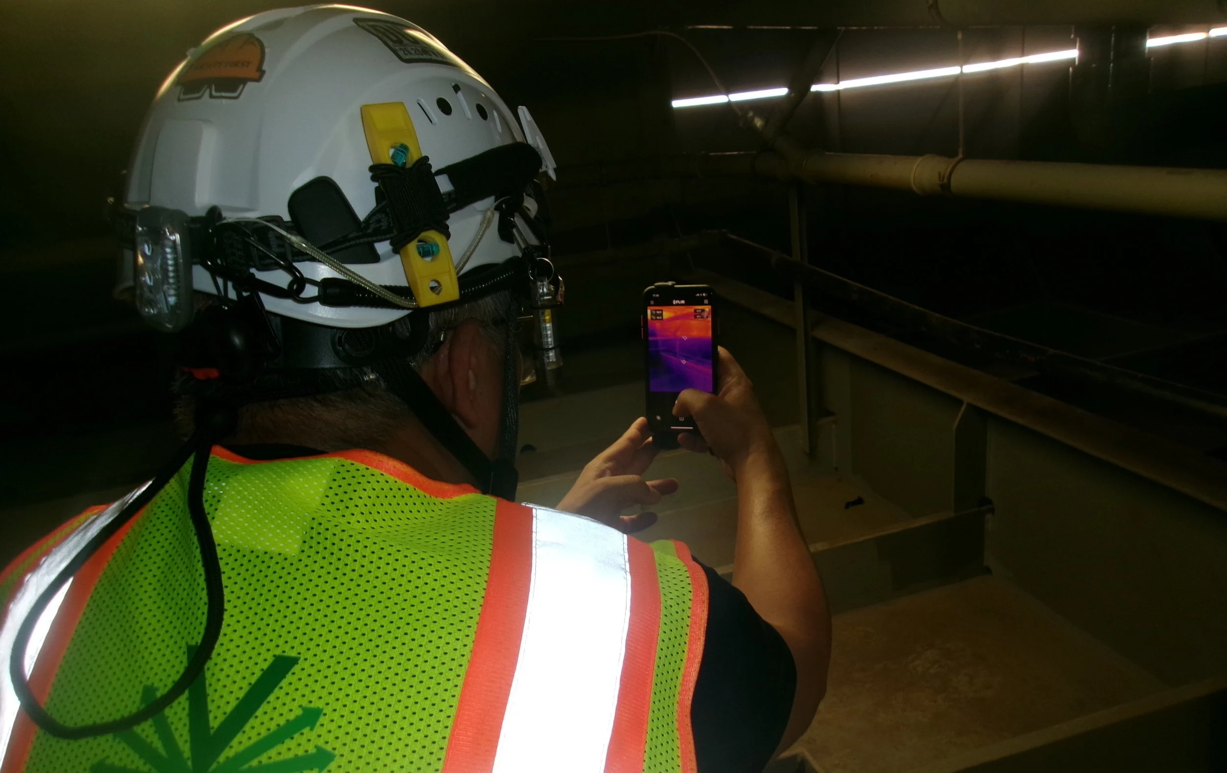
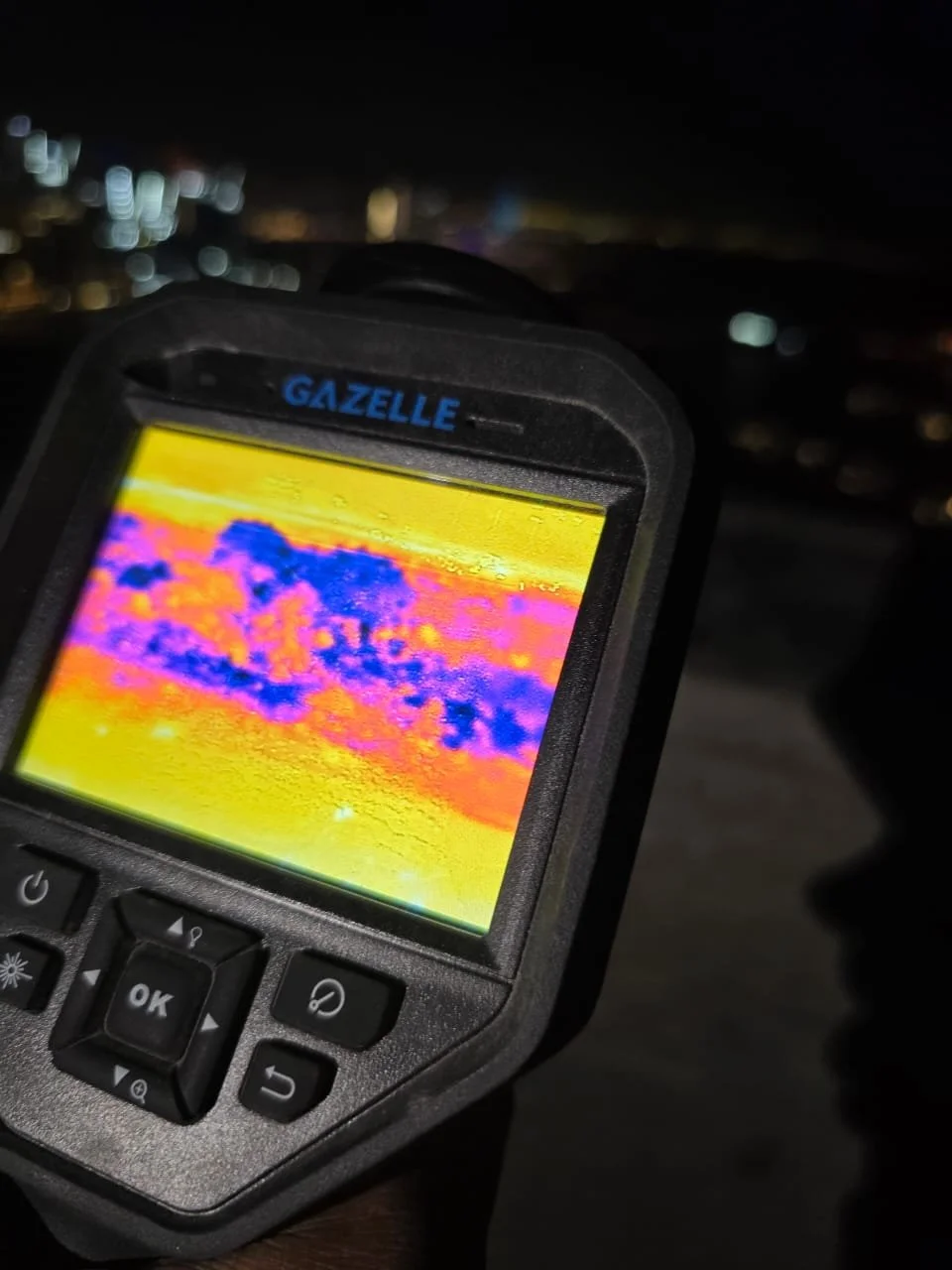
Identifies near-surface delamination in concrete across large areas quickly and effectively. As the sun heats the concrete surface, delaminated areas warm at a different rate than sound concrete, creating temperature differences that can be detected using infrared cameras. These results provide a clear visual map of deterioration and help estimate repair quantities.
Ultrasonic Thickness (UT)
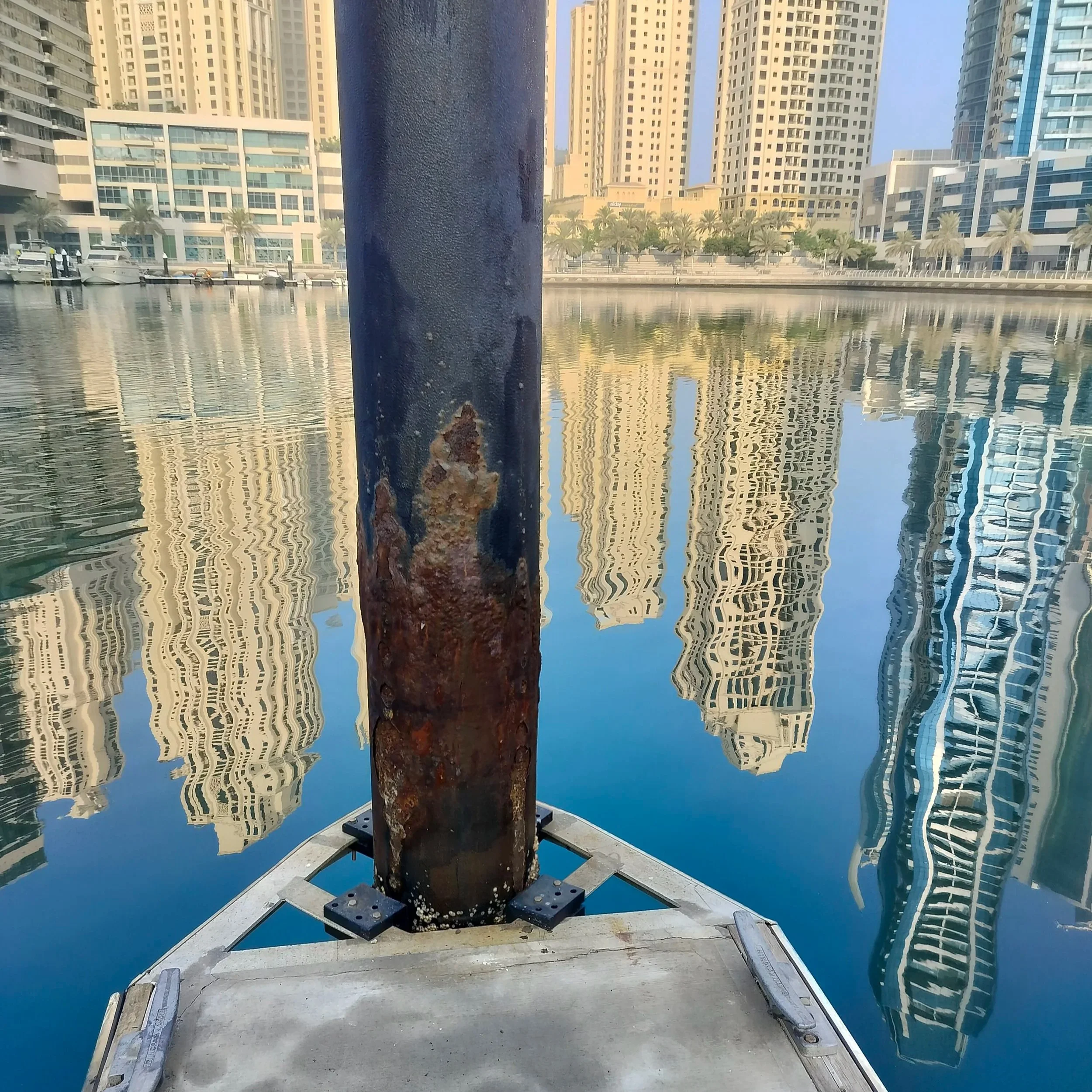
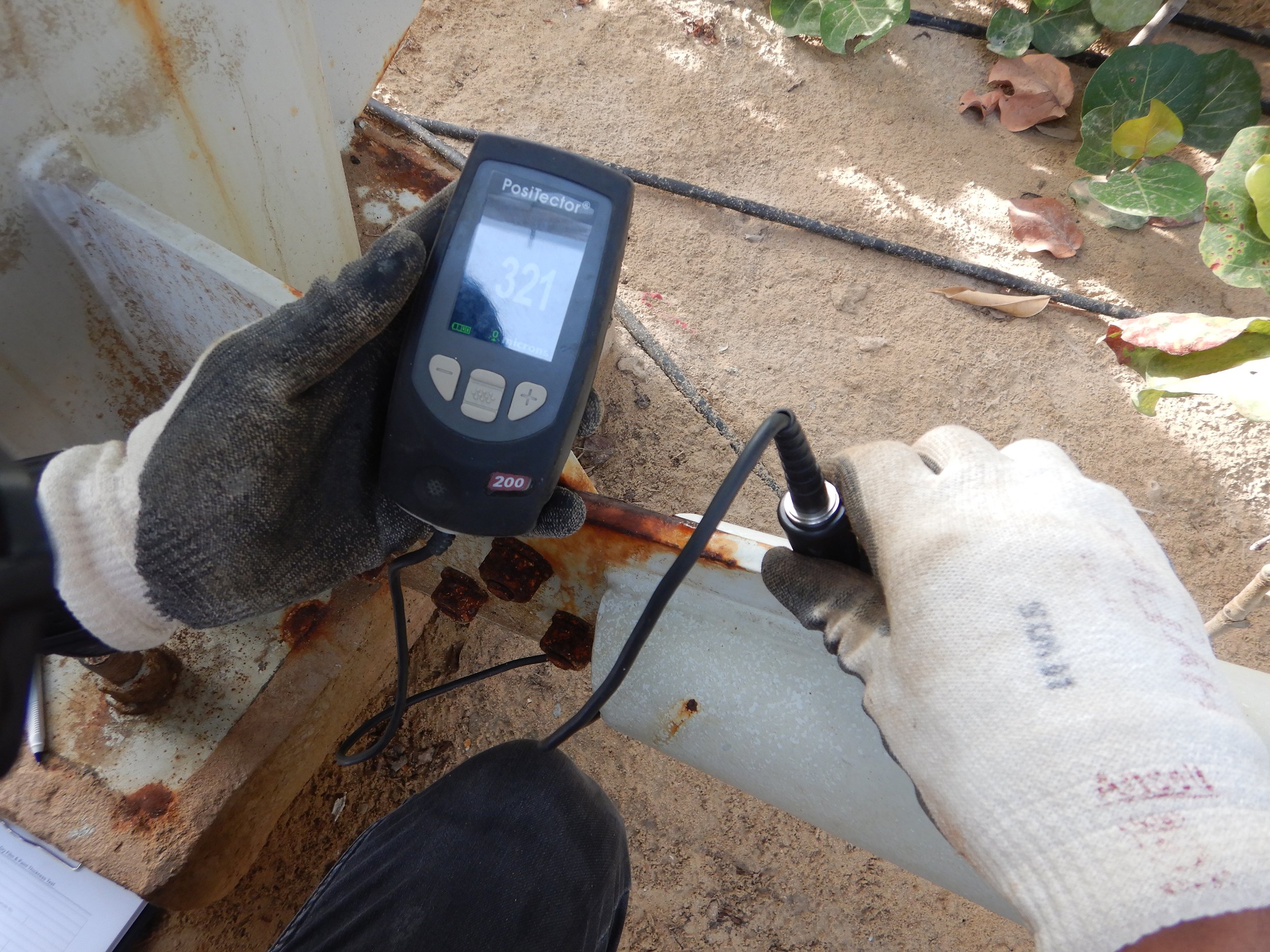
An ultrasonic thickness (UT) gauge is used to measure the thickness of steel elements. UT works by sending an ultrasonic signal through the steel and measuring how long it takes to travel through the material. This allows the remaining thickness to be determined and helps identify section loss caused by corrosion. When original thickness or age is known, this data can also be used to estimate the rate of section loss. UT can also be used to assess components such as bolts for section loss, cracking, or other defects.
Pile Length Testing
Determines the length of steel, wood, and concrete piles and helps identify potential defects along their depth. This method uses a hammer impact and sensors to measure how long it takes for a stress wave to travel down the pile and reflect back, providing insight into pile integrity and continuity. Changes in the signal can also indicate damage or defects along the pile.
Explore Our NDT Project Experience!